


1/6 F-105 Build Thread
 10-09-2018, 04:12 PM
#76

Thread Starter
My Feedback: (20)
I ordered servo mounting brackets and servos today so hopefully I can start doing some regular model airplane work soon.
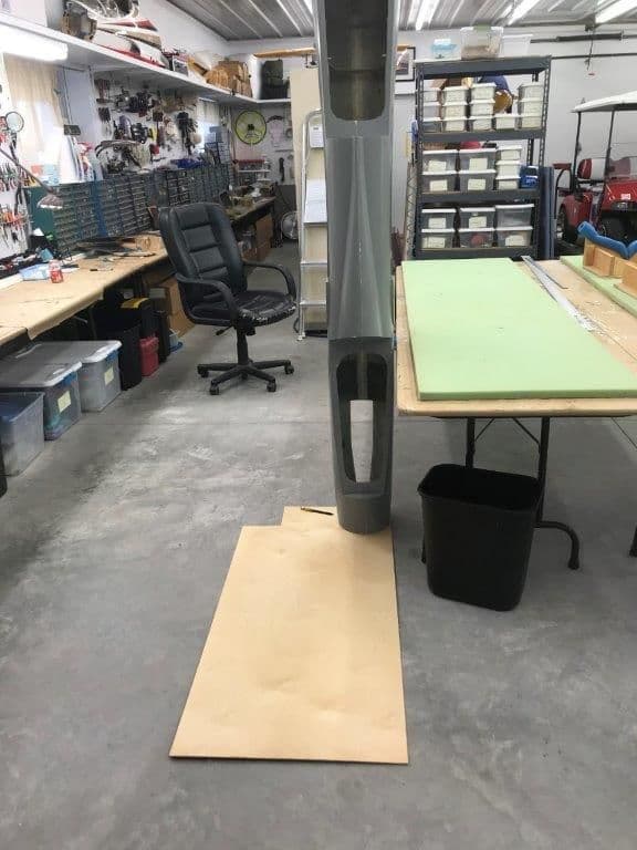
I got tired of messing around with mechanical issues on the gear and redesign of tail so I decided to do something drastic so I could see progress.
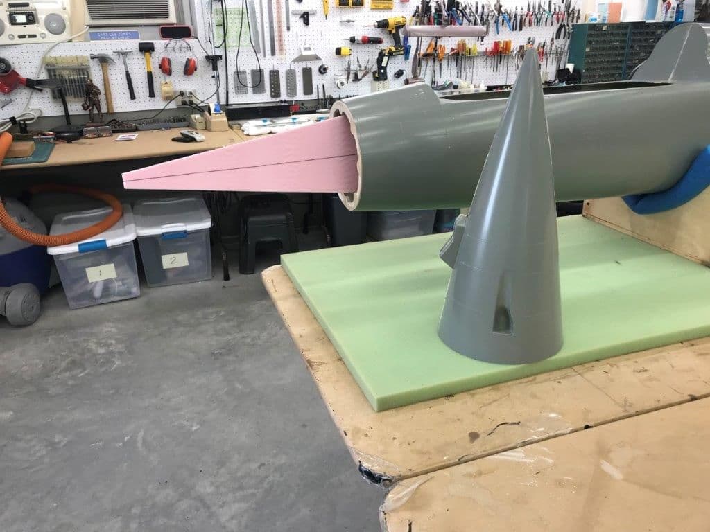
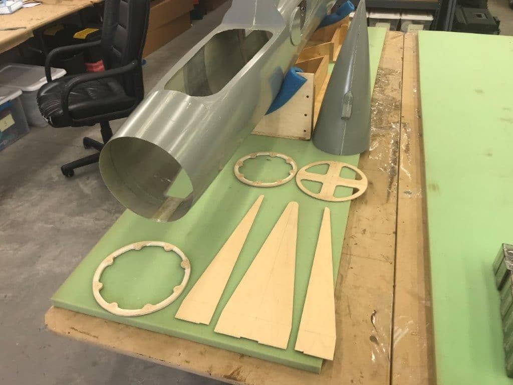
Sooo... I cut the nose and nozzle off. I had planned to do this earlier but just never got to it. The nose will be held on by carbon guide rods and magnets. I'm sure I will have to build a tray inside the nose to get weight as far forward as possible. Still thinking about how to attach the nozzle.
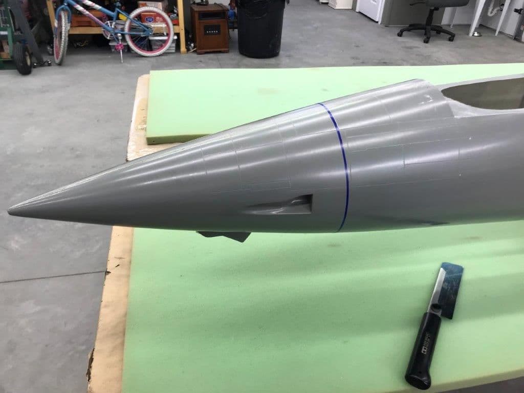
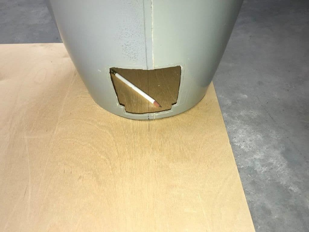
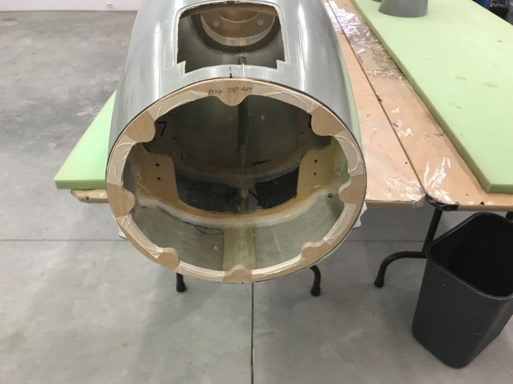
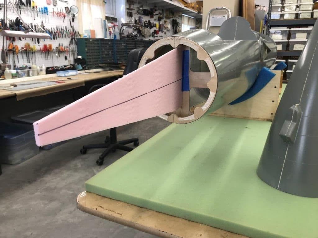
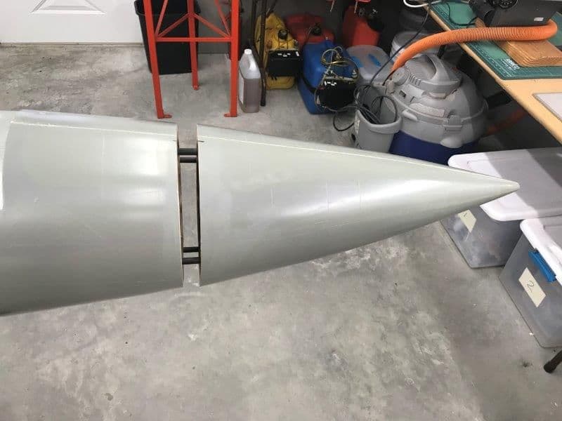
Cut line marked with 3M painting tape. The best panel line went right through the gun port and I did not want to cut up the gun port. I used that line as a reference, measured back to the next panel line on the top and marked the cut line there with 3M tape. I will doctor up the remaining panel lines during the finishing process.
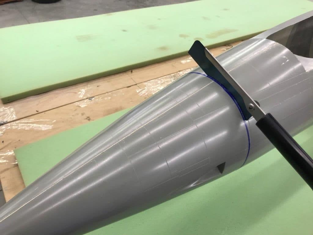
A razor backsaw use to make the cut
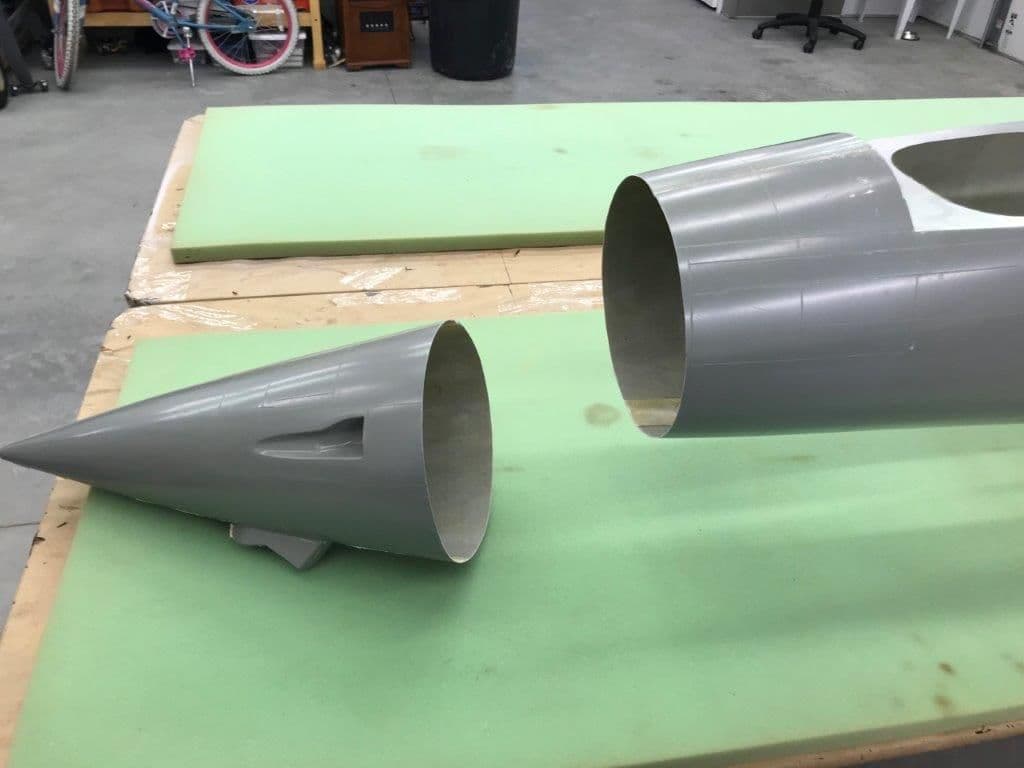
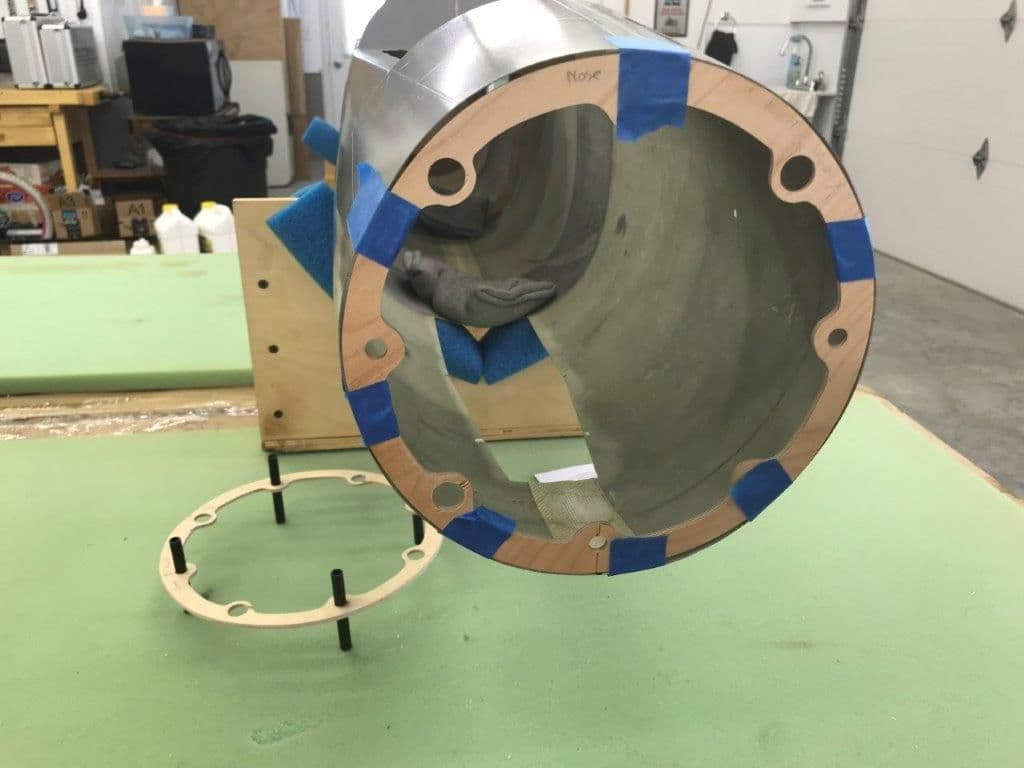
Nose cone off. It provides great access to the nose section now.
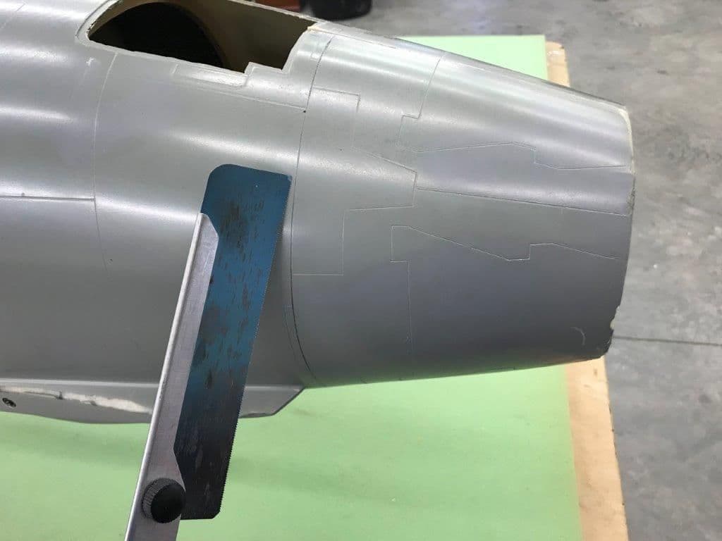
Nozzle panel line marked with pencil behind the drag chute door and ready to cut.
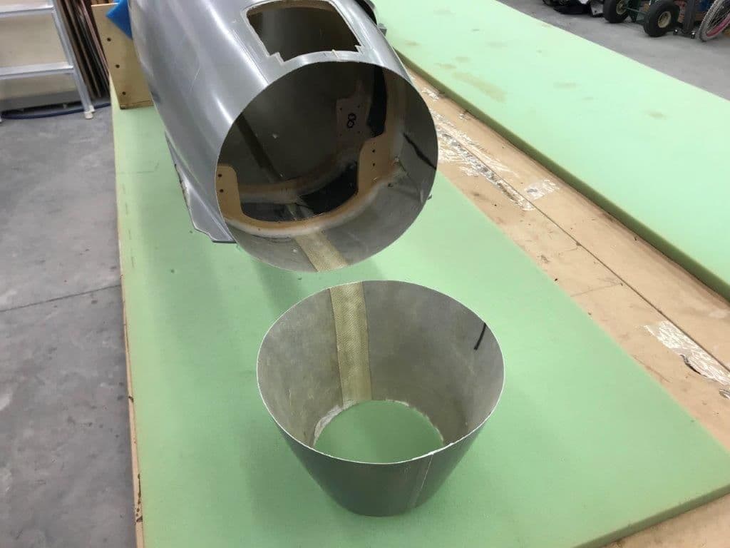
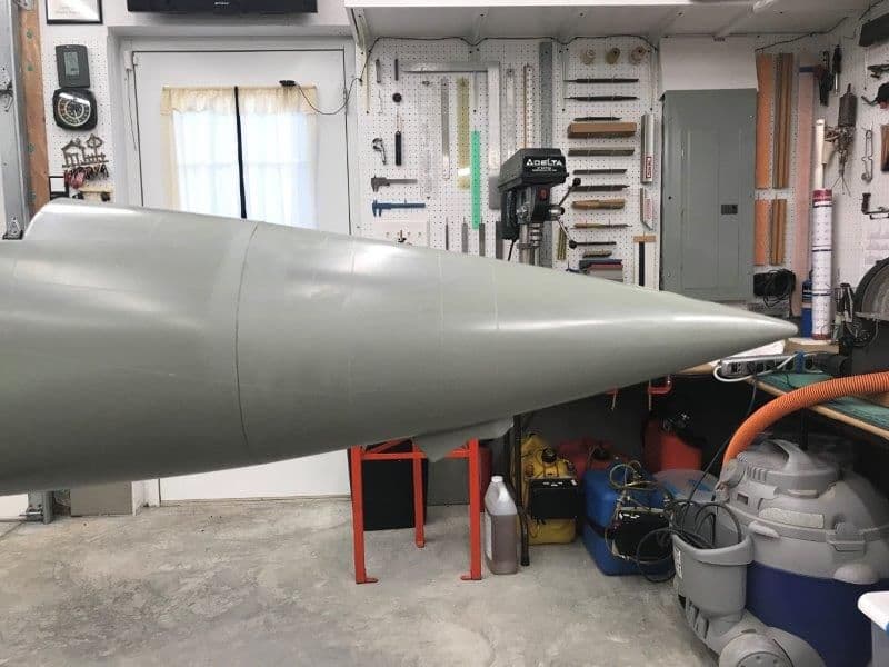
Nozzle removed. This will provide greater access to the stab area for the stab mount redesign. The pipe will be supported with a former at the cut line. The nozzle will not support the pipe.
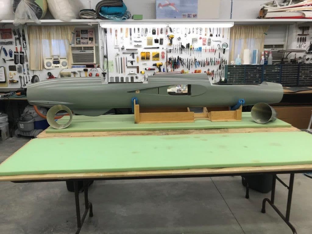
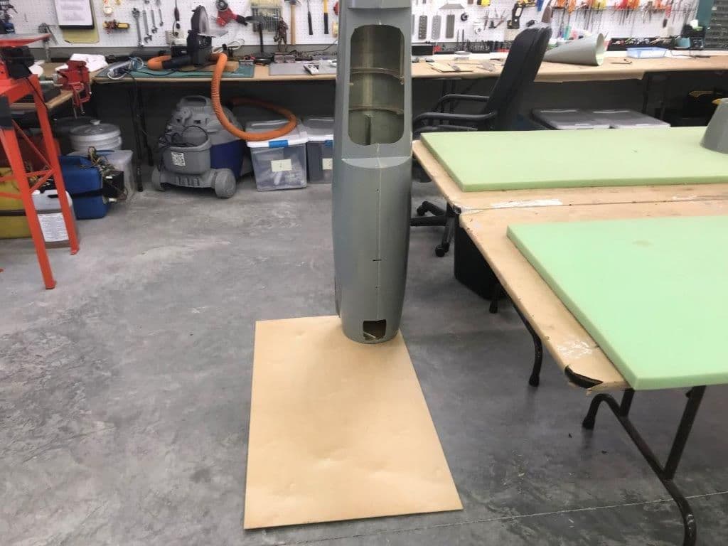
Fuse shorter now and better fits the 8' work table. Yea...visible progress!
I got tired of messing around with mechanical issues on the gear and redesign of tail so I decided to do something drastic so I could see progress.
Sooo... I cut the nose and nozzle off. I had planned to do this earlier but just never got to it. The nose will be held on by carbon guide rods and magnets. I'm sure I will have to build a tray inside the nose to get weight as far forward as possible. Still thinking about how to attach the nozzle.
Cut line marked with 3M painting tape. The best panel line went right through the gun port and I did not want to cut up the gun port. I used that line as a reference, measured back to the next panel line on the top and marked the cut line there with 3M tape. I will doctor up the remaining panel lines during the finishing process.
A razor backsaw use to make the cut
Nose cone off. It provides great access to the nose section now.
Nozzle panel line marked with pencil behind the drag chute door and ready to cut.
Nozzle removed. This will provide greater access to the stab area for the stab mount redesign. The pipe will be supported with a former at the cut line. The nozzle will not support the pipe.
Fuse shorter now and better fits the 8' work table. Yea...visible progress!

 10-10-2018, 03:38 PM
#78
Thread Starter
My Feedback: (20)
Hi Matt,
Its a Tamiya razor saw that I got at the LHS in Misawa, Japan when I was stationed there 1990-93. It has a replaceable blade. I really love it. It is sharp, keeps its edge, and has a very narrow kerf. Its easy to control. Great for fiberglass work. I have the spare blade I unwrapped for the photo. Have not needed it yet. Not sure if its still available or not.
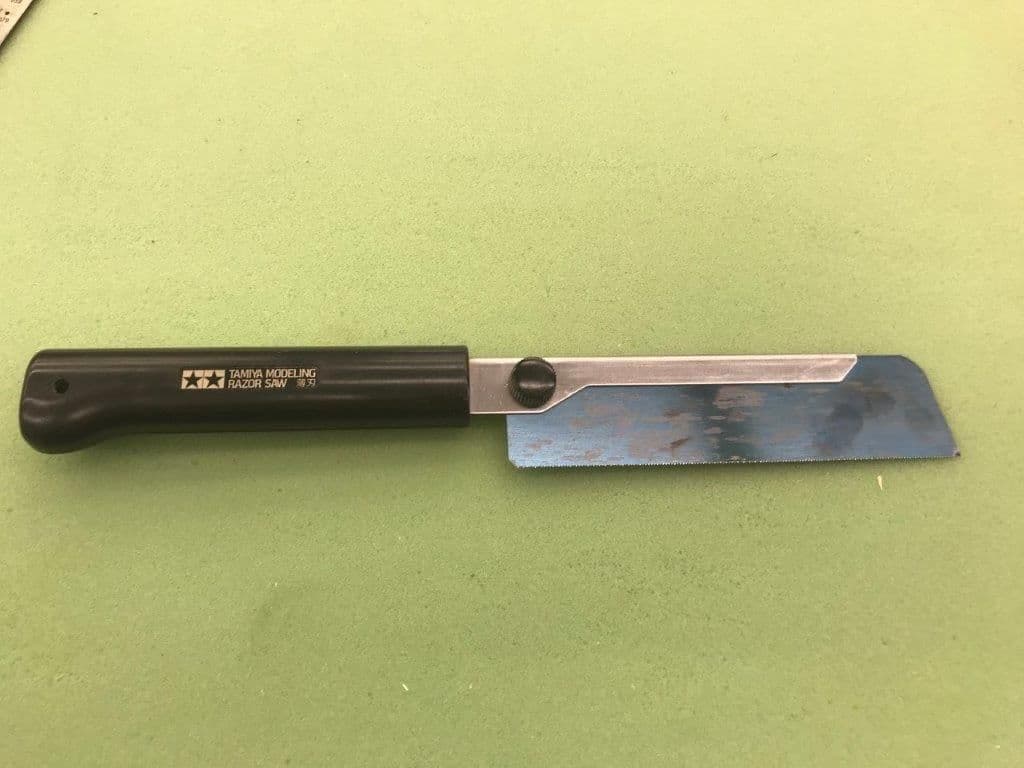
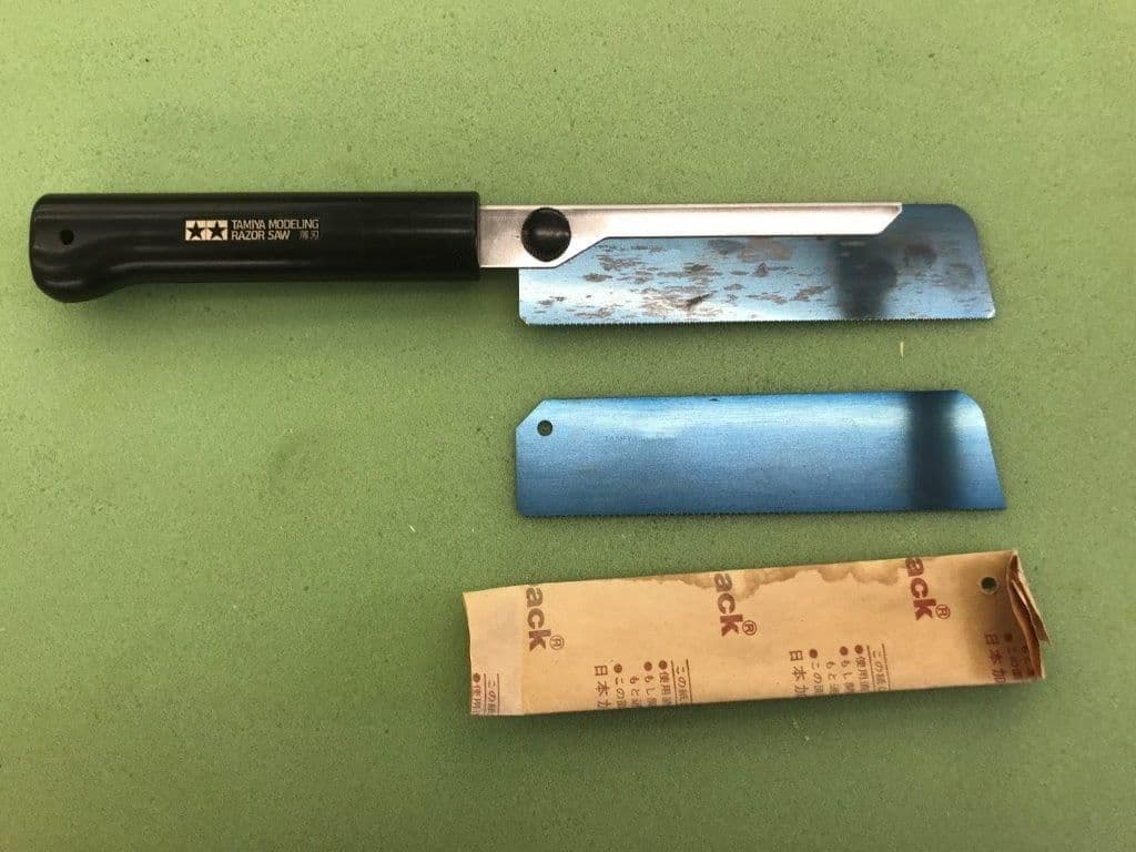
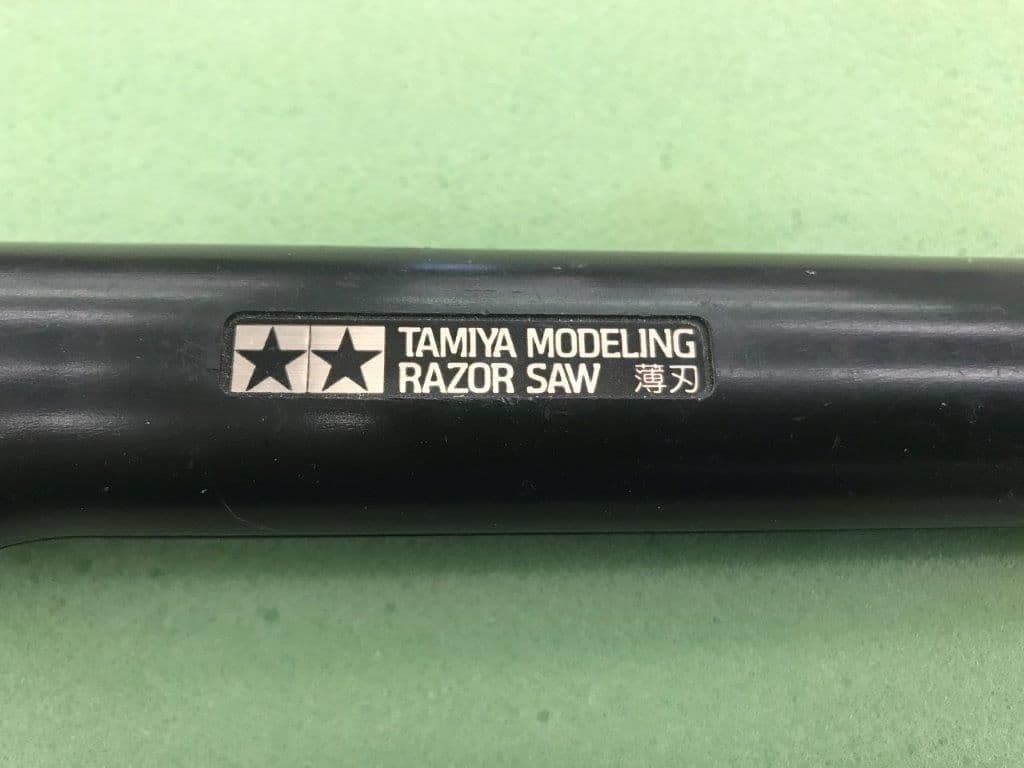
Its a Tamiya razor saw that I got at the LHS in Misawa, Japan when I was stationed there 1990-93. It has a replaceable blade. I really love it. It is sharp, keeps its edge, and has a very narrow kerf. Its easy to control. Great for fiberglass work. I have the spare blade I unwrapped for the photo. Have not needed it yet. Not sure if its still available or not.
10-10-2018, 03:51 PM
#79
Thread Starter
My Feedback: (20)
I've put the gear issues and stab redesign on the back burner for a while and am proceeding with some regular model airplane stuff which I can do myself in the shop. I can be thinking and researching solutions while working on "regular" scratch building stuff.
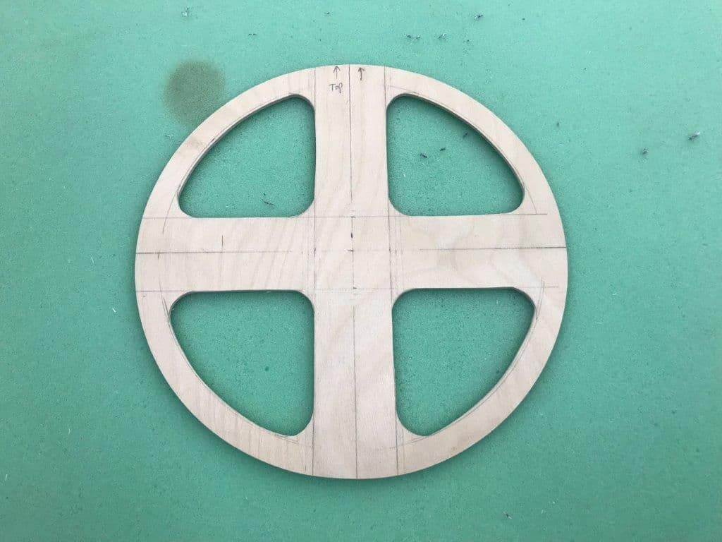
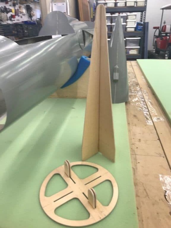
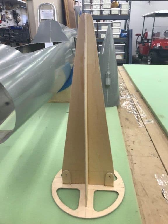
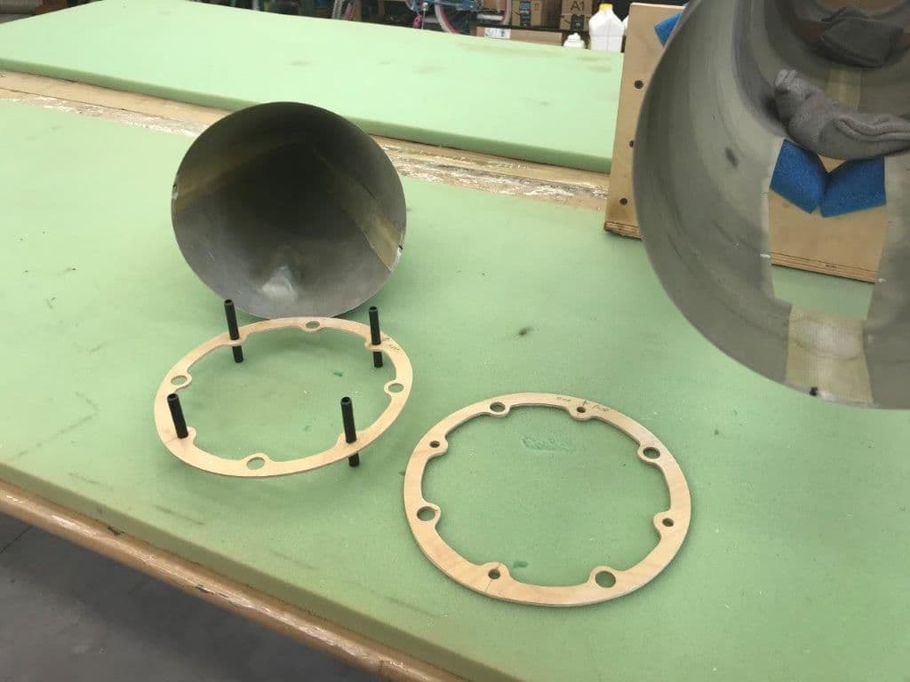
Today I designed and cut the 1/8" plywood formers that will hold the nose cone and nozzle to the fuse. I plan to make guide pins from 8mm carbon fiber tube and use rare earth magnets to hold on the nose cone. It should be easily removeable for servicing the jet. Same for the nozzle except I may use some safety screws if necessary.
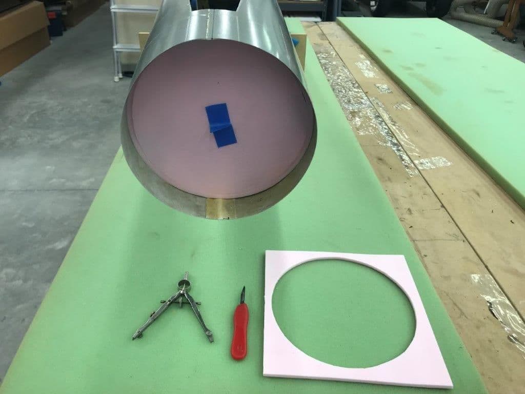
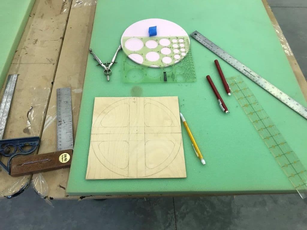
Step one, trace the pattern. I can now stand the thing up in the 9' ceiling shop after cutting off each end!
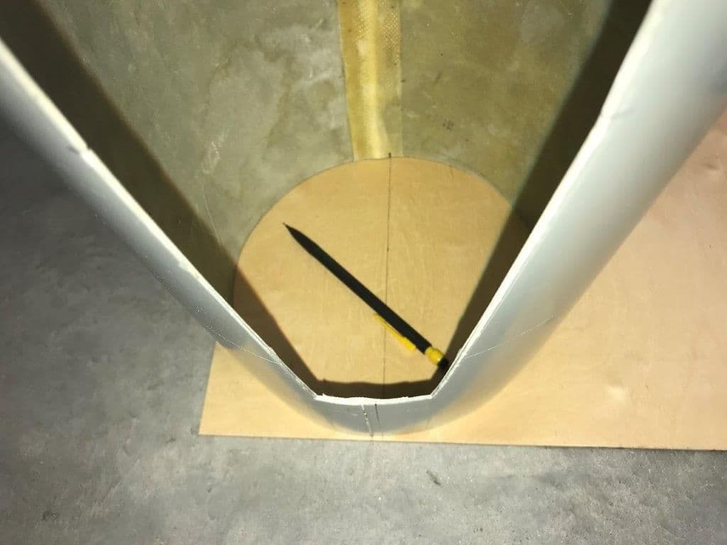
I had to establish the centerline on the fuse since the seam line is not the center. I wanted to trace on the inside to make an easier fit.
Nozzle former traced the same way.
Tracing done through the drag chute door.
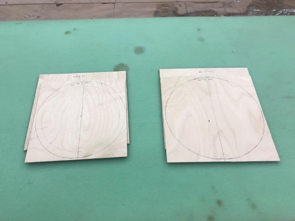
1/8" plywood blanks ready for pattern drawing layout and cutting
Today I designed and cut the 1/8" plywood formers that will hold the nose cone and nozzle to the fuse. I plan to make guide pins from 8mm carbon fiber tube and use rare earth magnets to hold on the nose cone. It should be easily removeable for servicing the jet. Same for the nozzle except I may use some safety screws if necessary.
Step one, trace the pattern. I can now stand the thing up in the 9' ceiling shop after cutting off each end!
I had to establish the centerline on the fuse since the seam line is not the center. I wanted to trace on the inside to make an easier fit.
Nozzle former traced the same way.
Tracing done through the drag chute door.
1/8" plywood blanks ready for pattern drawing layout and cutting
Last edited by Viper1GJ; 10-10-2018 at 03:56 PM.
10-10-2018, 04:07 PM
#80
Hey Gary I have a similar task to do on a nose cone, the tubes and magnets. How are you planning to line up the tubes so they are all parallel with each other? Any slick trick?
EDIT my idea was to glue the pins (or receptacles, does not matter which) on the nose cone side first.
On the inside of the cone, have some scrap rectangular (matched) stock hold the pins in place and parallel with each other while the glue dries. Then of course the nose cone jigs in the recepticles on the fuse side.
This sounds exhausting.......
Last edited by mr_matt; 10-10-2018 at 04:12 PM.
10-10-2018, 04:09 PM
#81
Thread Starter
My Feedback: (20)
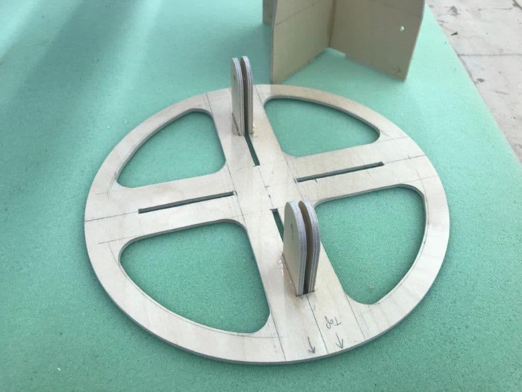
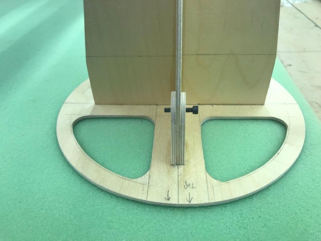
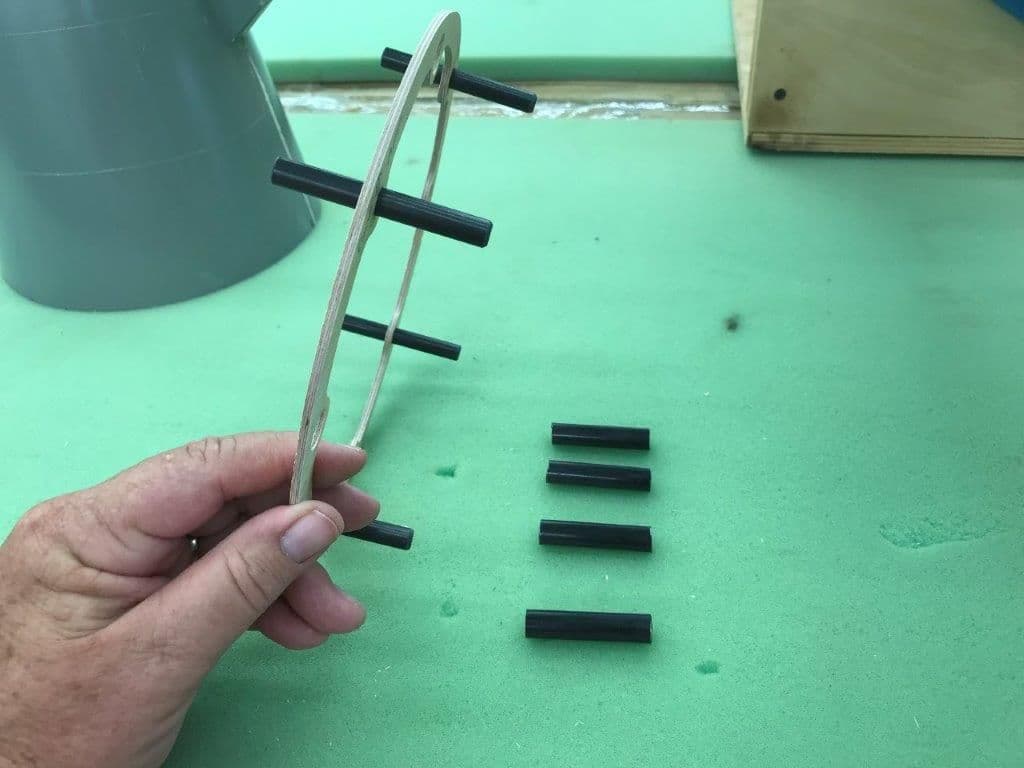
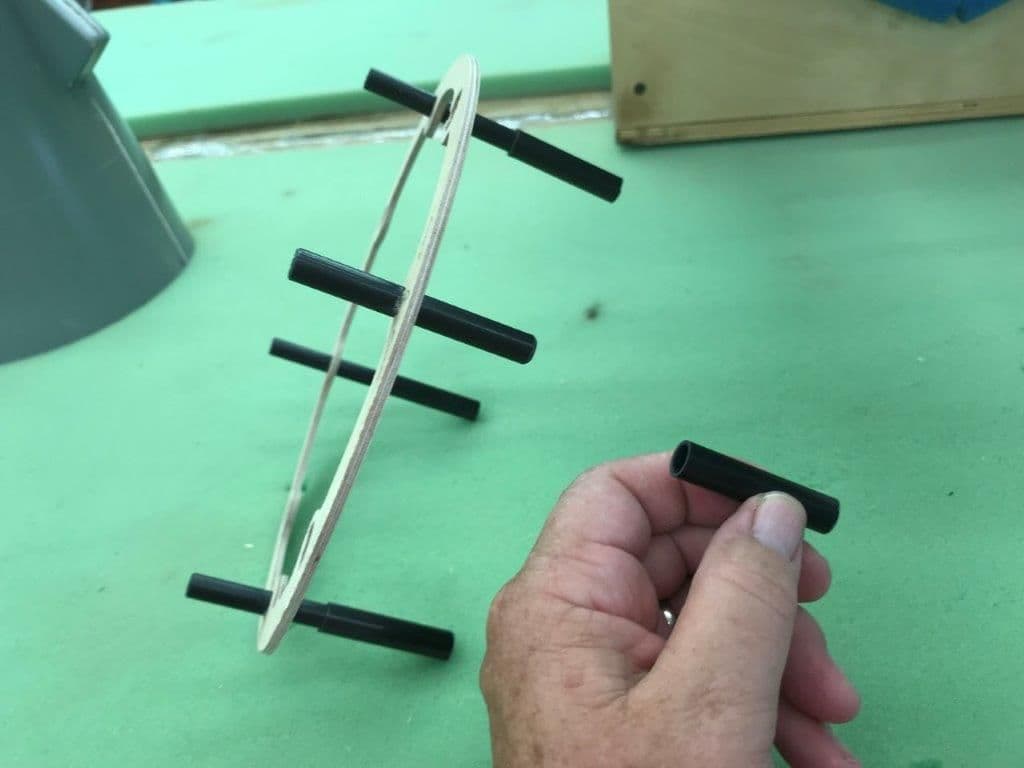
The design is to use 8mm carbon tube guide pins ant 10, 2, 4, and 8 and 1/2' x 1/8" magnet discs at 12, 3, 6, and 9
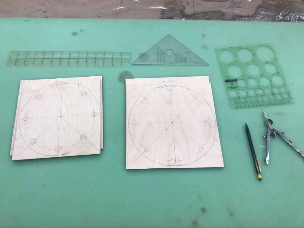
Layout done and ready to tape the blanks together to cut two identical formers at a time.
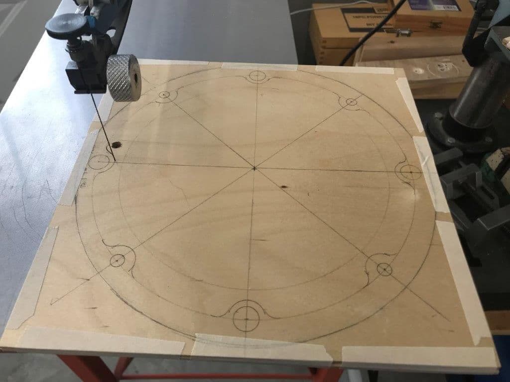
Scroll saw cutting started on inside cutout.
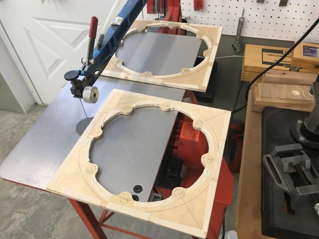
After inside cuts were complete tape was applied to the inside to keep the blanks together when outside cut made and tape falls off.
Formers cut out and ready for dry fit and drilling on drill press. I will leave the tape on until holes for the guide pins and magnets are drilled to ensure good alignment. Unfortunately that will be a few days because my magnets and carbon tubes have not arrived yet.
Layout done and ready to tape the blanks together to cut two identical formers at a time.
Scroll saw cutting started on inside cutout.
After inside cuts were complete tape was applied to the inside to keep the blanks together when outside cut made and tape falls off.
Formers cut out and ready for dry fit and drilling on drill press. I will leave the tape on until holes for the guide pins and magnets are drilled to ensure good alignment. Unfortunately that will be a few days because my magnets and carbon tubes have not arrived yet.
10-10-2018, 04:17 PM
#83
Thread Starter
My Feedback: (20)
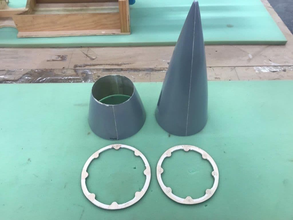
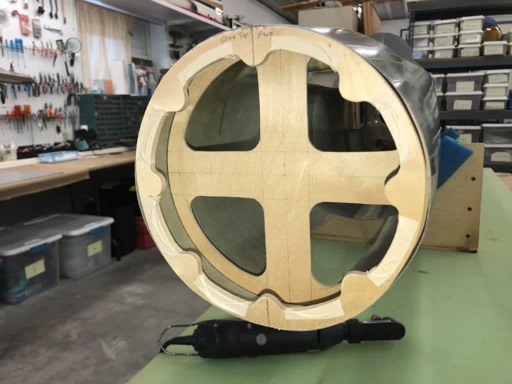
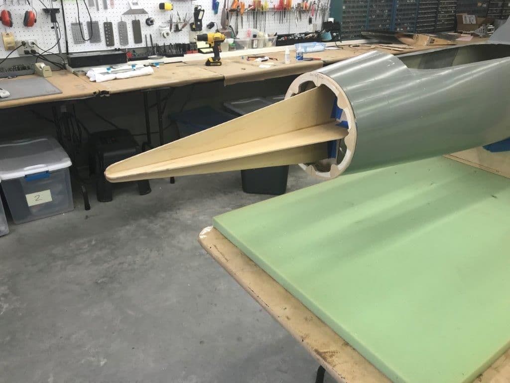
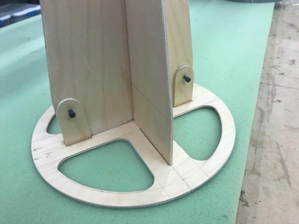
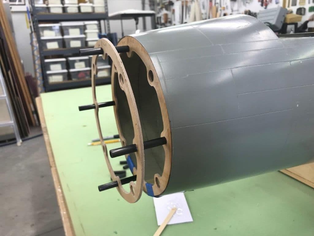
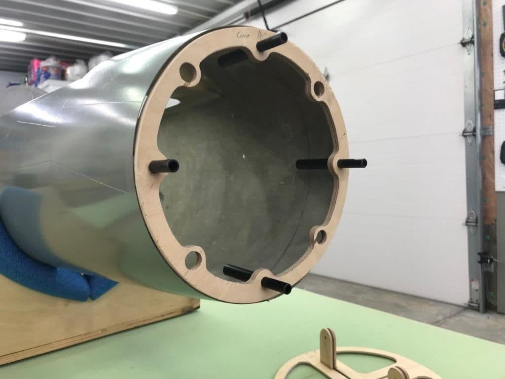
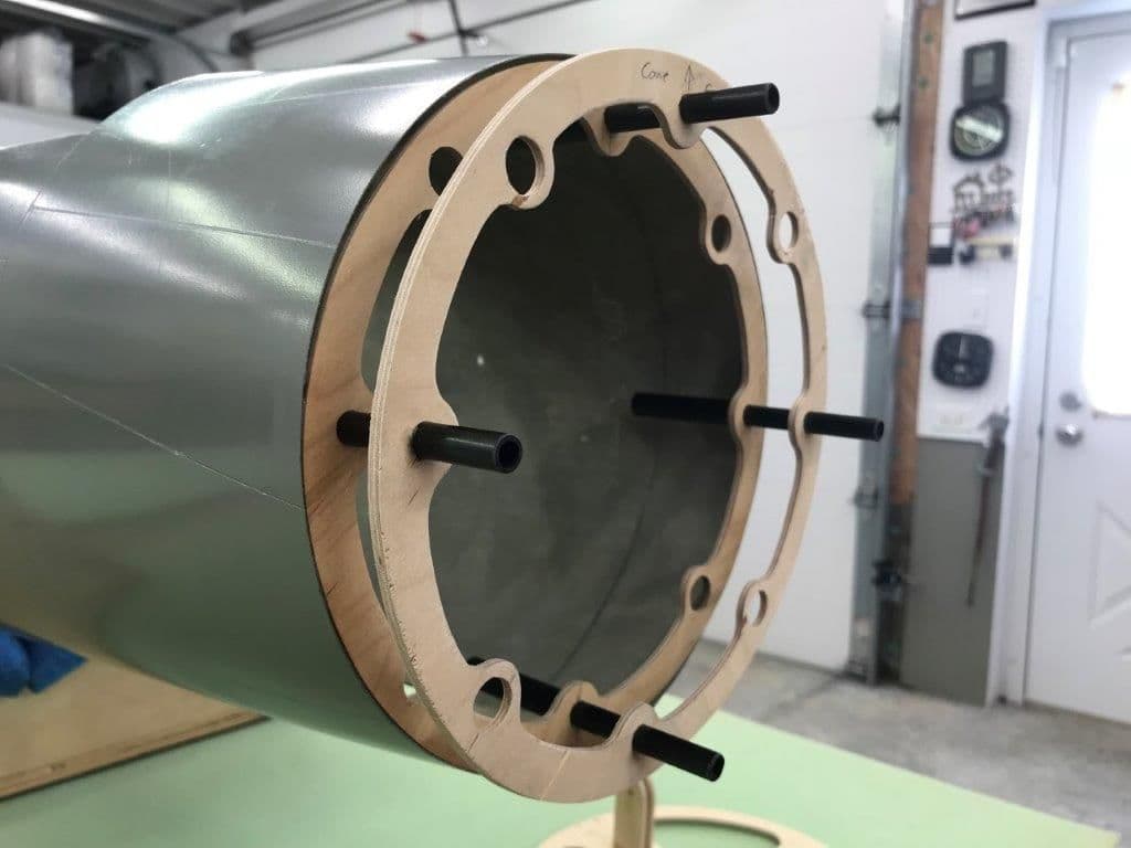
Initial dry fits looked OK. Some minor sanding needed in spots will make fits perfect. I'll keep the tape on each set of formers until I can drill the holes to fit the tubes and magnets.
 se
se
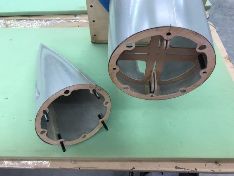
Front of fuse looking aft.
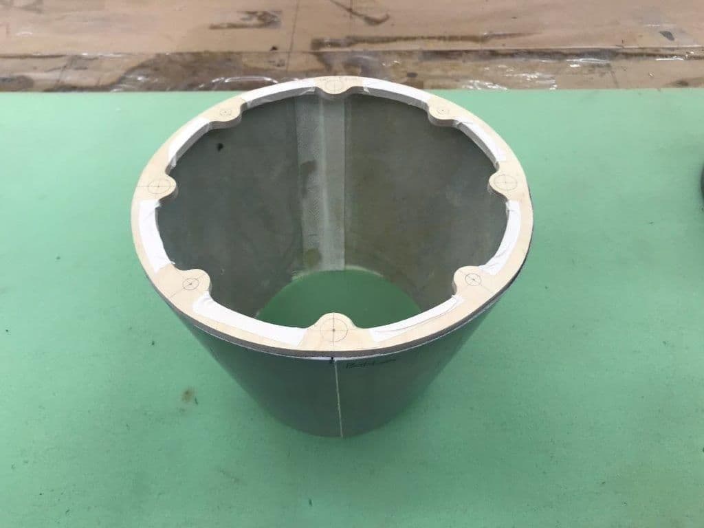
Nose cone fit
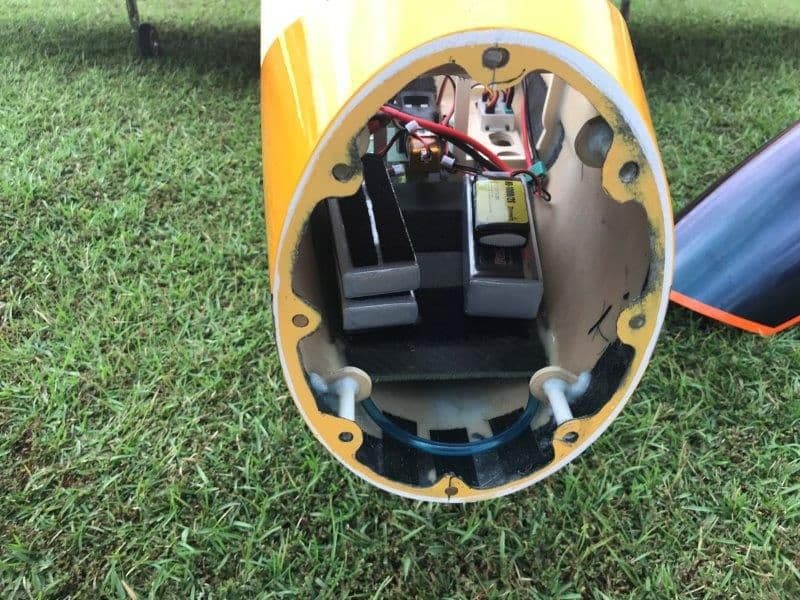
Tail of fuse looking forward. Now there is easy access to the stab formers and for install of the vertical fin former. Also my pipe can now be installed with bell mouth attached instead of having to remove it and reattach it in the turbine bay.
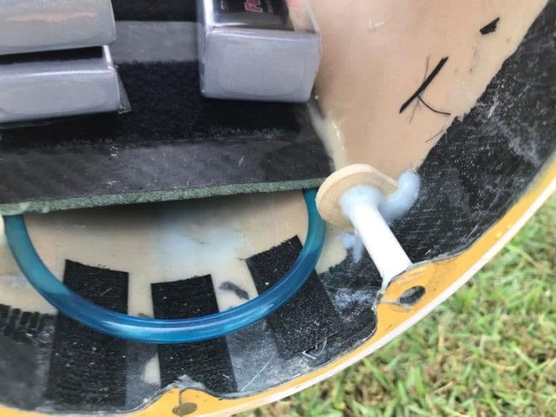
Nozzle dry fit.
seFront of fuse looking aft.
Nose cone fit
Tail of fuse looking forward. Now there is easy access to the stab formers and for install of the vertical fin former. Also my pipe can now be installed with bell mouth attached instead of having to remove it and reattach it in the turbine bay.
Nozzle dry fit.
10-10-2018, 04:45 PM
#84
Thread Starter
My Feedback: (20)
Matt,
This is what i'm trying to do. I saw this on an ARF jet at SJS last week.
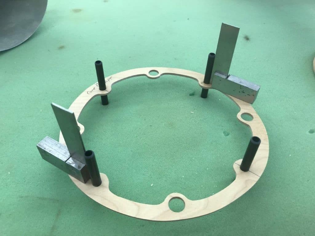
I had planned to drill all the holes in both formers together to get parallel holes. Then tack in the carbon guide pins on the nose cone side using CA and a small metal square to ensure they are square with the former. Then place the two formers together and tack in the sleeves on the back of the fuse former using the guide pins for alignment. Then place the formers together in the fuse and tack in the fuse former. Then check that the front former slides in and out OK. Then tack the nose cone to the front former. After everything is aligned and works ok then hysol everything and add braces on the sleeves and guide pins. Well, that's the plan, and of course you know plans never survive first contact with wood and glue! We will see.
This is what i'm trying to do. I saw this on an ARF jet at SJS last week.
I had planned to drill all the holes in both formers together to get parallel holes. Then tack in the carbon guide pins on the nose cone side using CA and a small metal square to ensure they are square with the former. Then place the two formers together and tack in the sleeves on the back of the fuse former using the guide pins for alignment. Then place the formers together in the fuse and tack in the fuse former. Then check that the front former slides in and out OK. Then tack the nose cone to the front former. After everything is aligned and works ok then hysol everything and add braces on the sleeves and guide pins. Well, that's the plan, and of course you know plans never survive first contact with wood and glue! We will see.


 10-12-2018, 04:09 PM
#87
Thread Starter
My Feedback: (20)
Hi David,
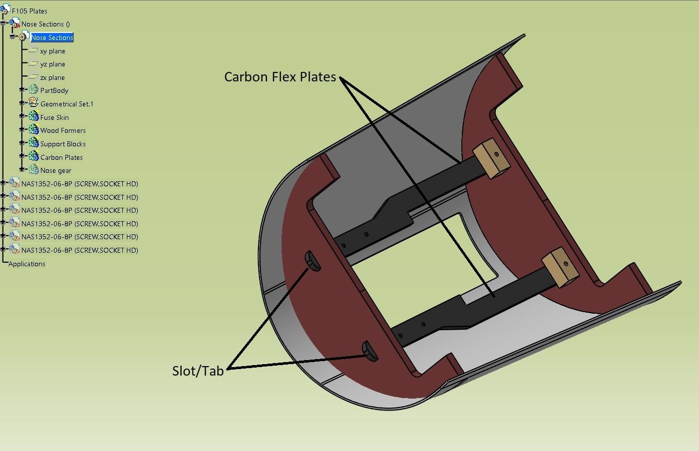
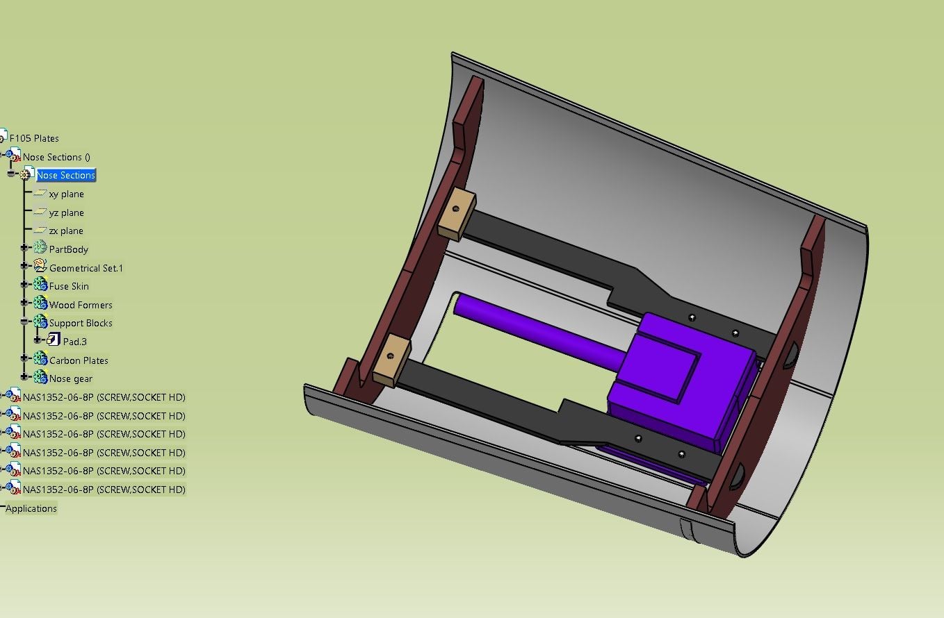
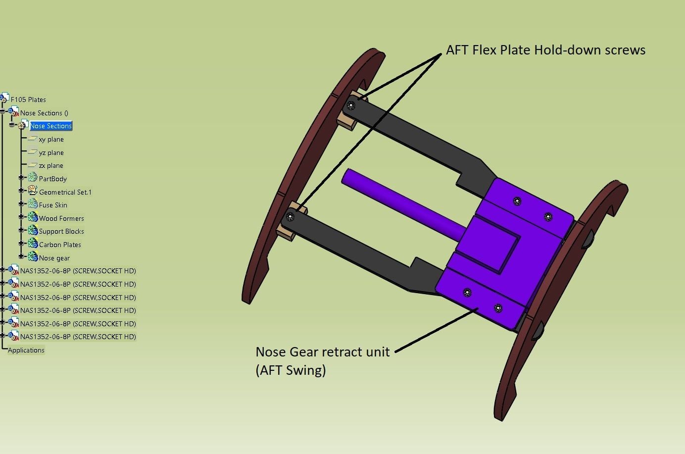
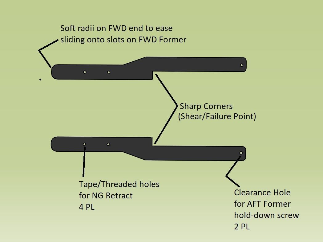
Thanks for the flex plate ideas. I see how they would work now but I think my nose gear mount is so long there would not be much flexing available. My gear mount frame is about 7" long and the distance between the formers is 8". Most of the stress would be just transmitted to the formers at the end of the flex plates instead of flexing. See the photo in post #40. You sketches did give me an idea about how to make clearance for my nose gear offset door hinges. Many thanks for the suggestion.
Do you fly with the Thunderbirds RC Club in Ft Worth? I flew there when I retired from the Air Force at the Lockheed F-16 factory in 1995 before they moved the RC field to the current location.
Gary
10-12-2018, 04:37 PM
#88
Thread Starter
My Feedback: (20)
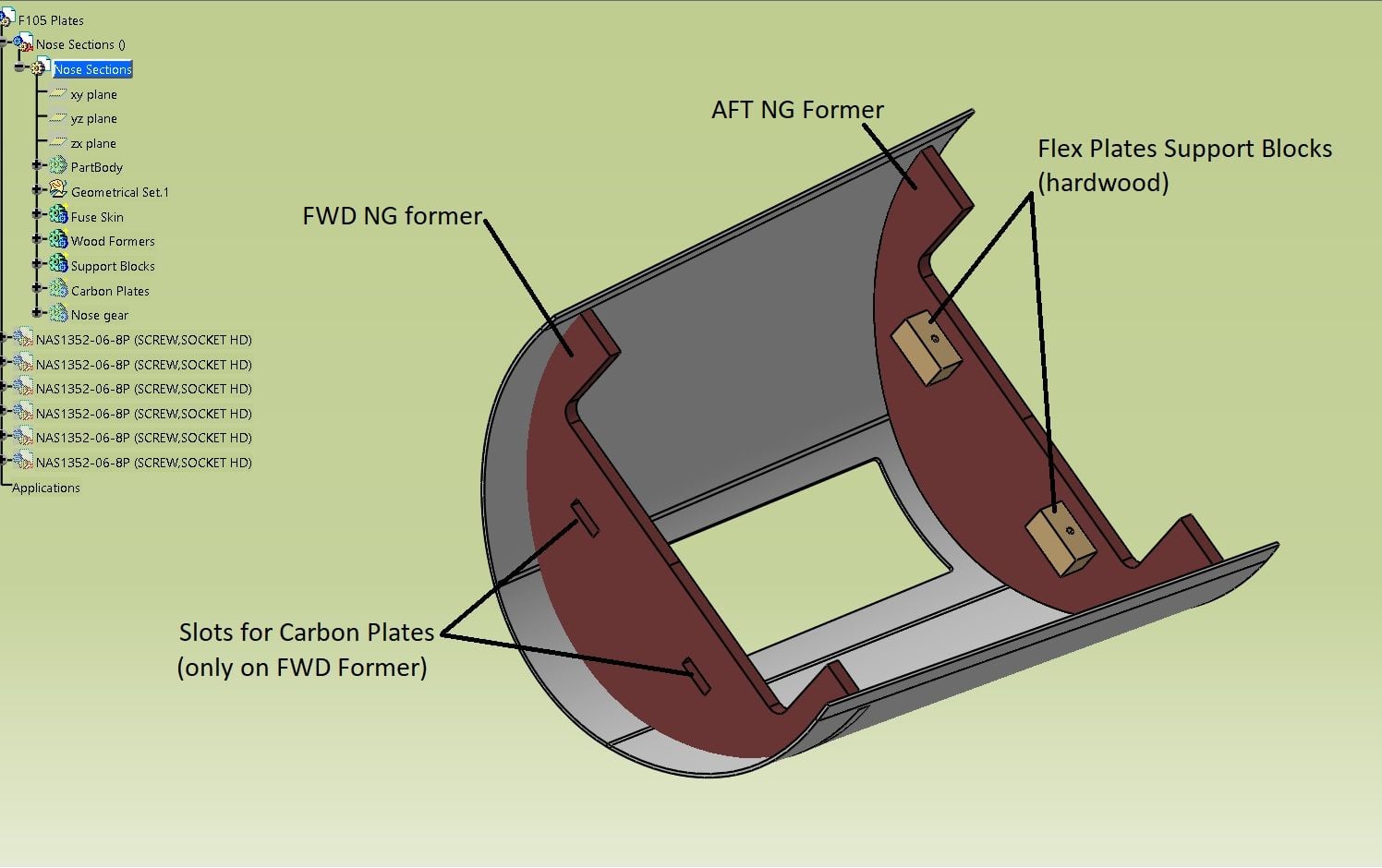
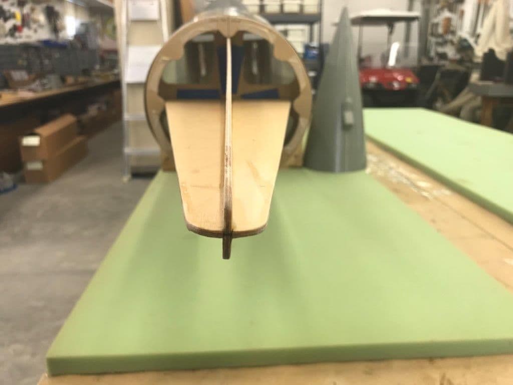
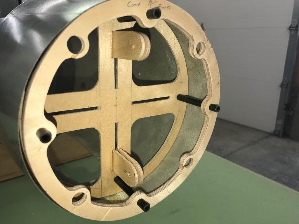
Not much done the last couple of days. Hurricane Michael prep, storm related power failure for a day, and clean up took most of the week. I did get time to fabricate the nose equipment tray and former. The former will greatly stiffen the fuse forward of the nose gear doors and provide a mount for the removable nose equipment tray. I wanted it about 2" behind the front former to stiffen the fuse just forward of the nose gear door cutout and to mount the nose cone guide pin sleeves between the front former and the equipment tray former.
Pink foam use to mock up former. My first cut was too small so I taped it back together and made a larger cut that worked out good. You can see the cut line around the edge.
Former designed on the plywood using CAD before cutting. This "CAD" is called "Come Along Design" as the design "comes along" as I think it up or copy somebody else's work and the pieces get marked and cut! The only problem is that the plans disappear as they get glued into the airplane!
Former cut out
First dry fit 2" behind the front former.
10-12-2018, 04:47 PM
#89
Thread Starter
My Feedback: (20)
Nose tray parts cut
Pink foam used to mock up nose tray parts
Space between the formers is for the nose cone guide pin sleeves
Parts cut and ready to assemble. I did not bother to make lightening holes since I will be adding batteries and probably lead on the tray anyway.
Tray parts glued together and taped to former for test fit
Lots of room for LEAD at the front. Hope not but we will see.
10-12-2018, 04:57 PM
#90
Thread Starter
My Feedback: (20)
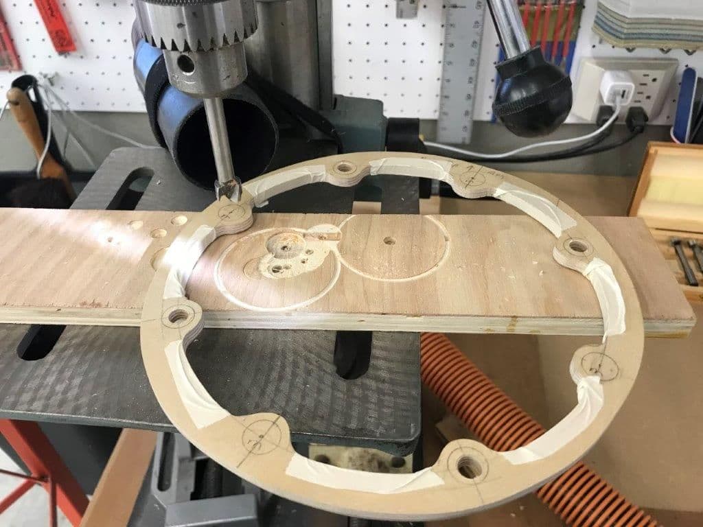
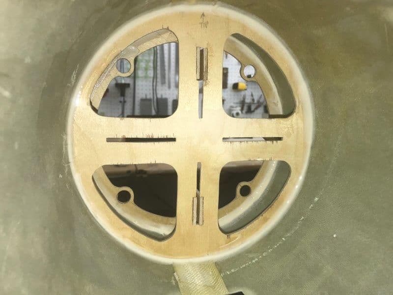
Slots were cut in the former and plywood mounting lugs cut out, drilled, and glued to former
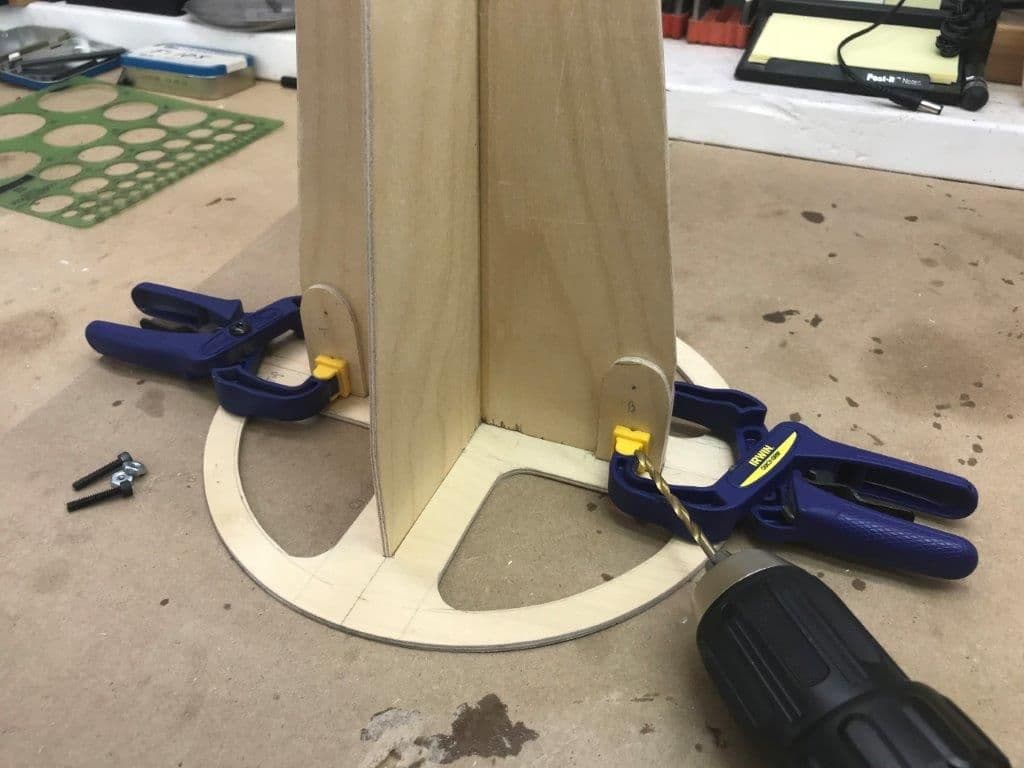
Plywood mounting lugs clamped and drilled. After drilling bolts were added and lugs glued to former with medium CA. All joints will get hysol after everything is completed and working.
Former and tray ready to assemble
Test fit after gluing
Joints ready for hysol after all nose parts are assembled and tested
6-32 bolts will get blind nuts and rubber sealing washers when done
Tray will fit into notches and get clamped between the mounting lugs
 10-14-2018, 02:55 PM
#92
Hi David,
Thanks for the flex plate ideas. I see how they would work now but I think my nose gear mount is so long there would not be much flexing available. My gear mount frame is about 7" long and the distance between the formers is 8". Most of the stress would be just transmitted to the formers at the end of the flex plates instead of flexing. See the photo in post #40. You sketches did give me an idea about how to make clearance for my nose gear offset door hinges. Many thanks for the suggestion.
Do you fly with the Thunderbirds RC Club in Ft Worth? I flew there when I retired from the Air Force at the Lockheed F-16 factory in 1995 before they moved the RC field to the current location.
Gary
10-14-2018, 03:51 PM
#93
Thread Starter
My Feedback: (20)
Yes I do, our new field is now on the south side of the lake. Very nice facilities. I also work for Skunk Works at the F-16 factory. I'm currently assisting on the development of the F-16V. Though I've worked almost every modern military platform, deep inside I'm a Viper guy. ����
I flew at the Thunderbirds field till 1997 when I moved to Denver for the airline job.
10-14-2018, 04:23 PM
#94
Thread Starter
My Feedback: (20)
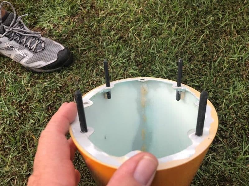
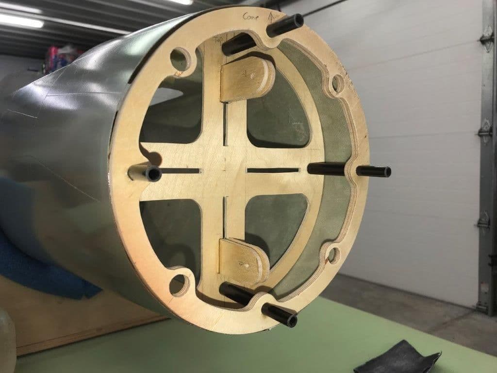
Started installing nose formers and nose cone guide pins today. I got the carbon tubes and magnets over the weekend so all the parts needed are in. The 8mm guide pin tubes fit inside the 10mm tubes perfectly so I did not have to make my own sleeves for the guide pins
I realized my Come Along Design "CAD" plans did not come far enough to allow any material on the second former to mount the 10mm sleeves on so I changed the design a little. I rotated the front formers so the guide pins are at 12, 3, 6, and 9. This will allow the carbon tube sleeves to contact the nose tray former without mods. You guys with real CAD would have figured that out on screen real fast. Alass...old school cut and paste, sometimes cut twice and still have to paste.
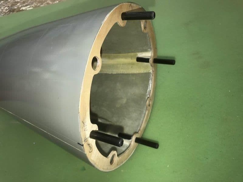
Nose formers drilled for 1/2" magnets. Guide pin holes are for 8mm carbon tubes
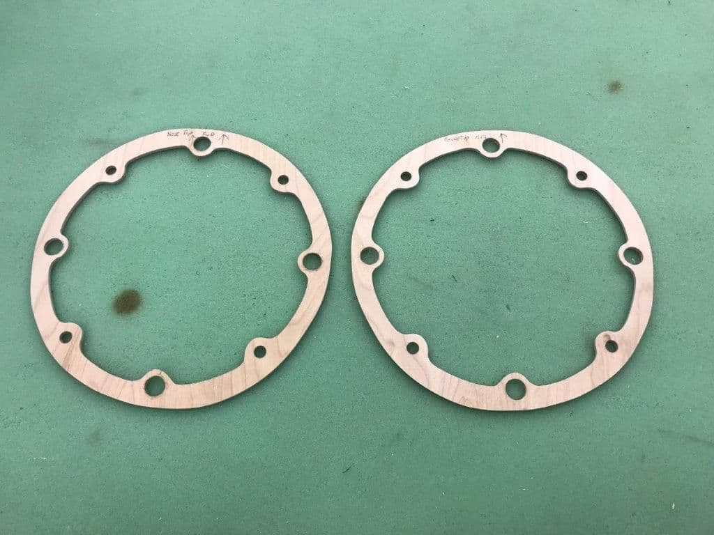
All holes drilled ready for dry fits
8mm carbon tubes cut and beveled on one end to engage the 10mm tube sleeves
Guide pins inserted to nose cone former
Pins squared with former and tacked on with drop of med CA
Formers dry fit before gluing in
I realized my Come Along Design "CAD" plans did not come far enough to allow any material on the second former to mount the 10mm sleeves on so I changed the design a little. I rotated the front formers so the guide pins are at 12, 3, 6, and 9. This will allow the carbon tube sleeves to contact the nose tray former without mods. You guys with real CAD would have figured that out on screen real fast. Alass...old school cut and paste, sometimes cut twice and still have to paste.
Nose formers drilled for 1/2" magnets. Guide pin holes are for 8mm carbon tubes
All holes drilled ready for dry fits
8mm carbon tubes cut and beveled on one end to engage the 10mm tube sleeves
Guide pins inserted to nose cone former
Pins squared with former and tacked on with drop of med CA
Formers dry fit before gluing in
10-14-2018, 04:39 PM
#95
Thread Starter
My Feedback: (20)
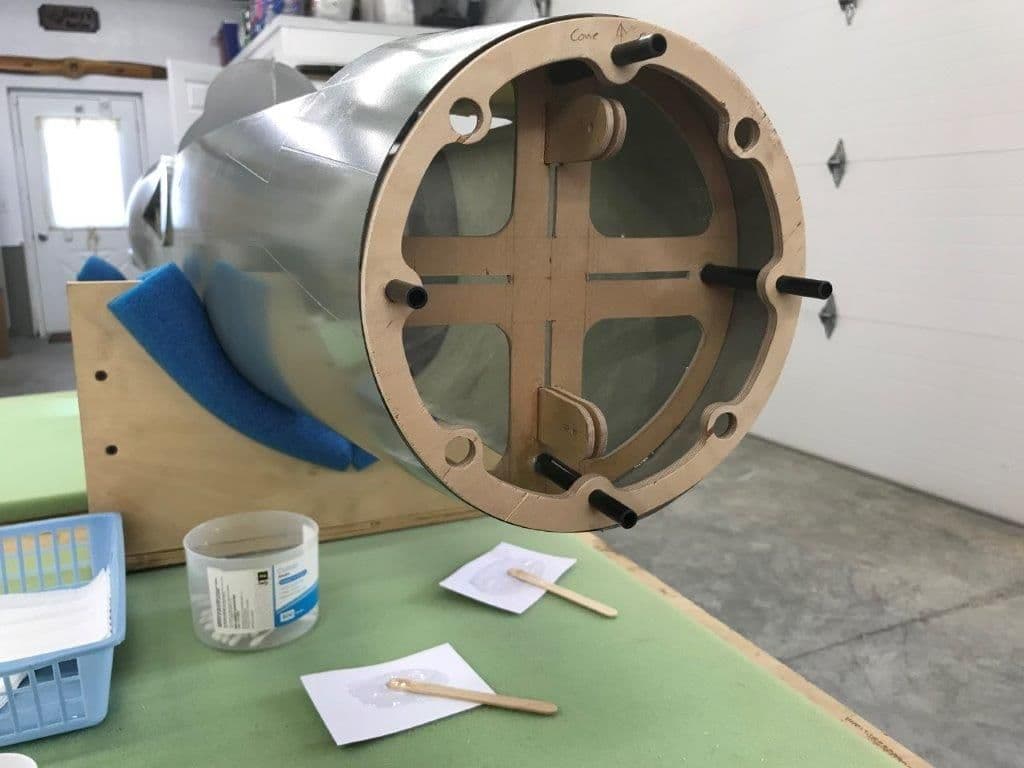
I use 5 min epoxy and CA to tack the parts together just in case I needed to bust it apart if it didn't work.
Ready to tack glue front former with 5 min epoxy.
Front former tacked in and taped
Guide pins inserted while epoxy cures
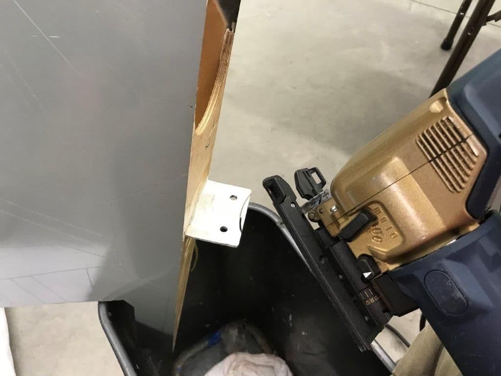
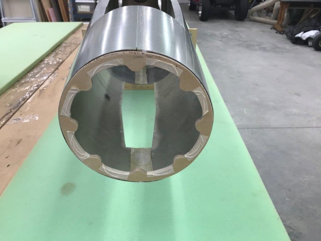
While waiting for epoxy to cure I cut the wing spar relief cuts for the air intake with a jig saw. Fortunately the saw fit and would make the cut.
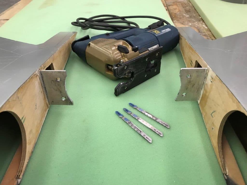
Unfortunately the aluminum was hard enough to destroy 3 new metal cut blades making about 5" of cut. But its done just needs smoothing out.
Ready to tack glue front former with 5 min epoxy.
Front former tacked in and taped
Guide pins inserted while epoxy cures
While waiting for epoxy to cure I cut the wing spar relief cuts for the air intake with a jig saw. Fortunately the saw fit and would make the cut.
Unfortunately the aluminum was hard enough to destroy 3 new metal cut blades making about 5" of cut. But its done just needs smoothing out.
10-14-2018, 04:53 PM
#96
Thread Starter
My Feedback: (20)
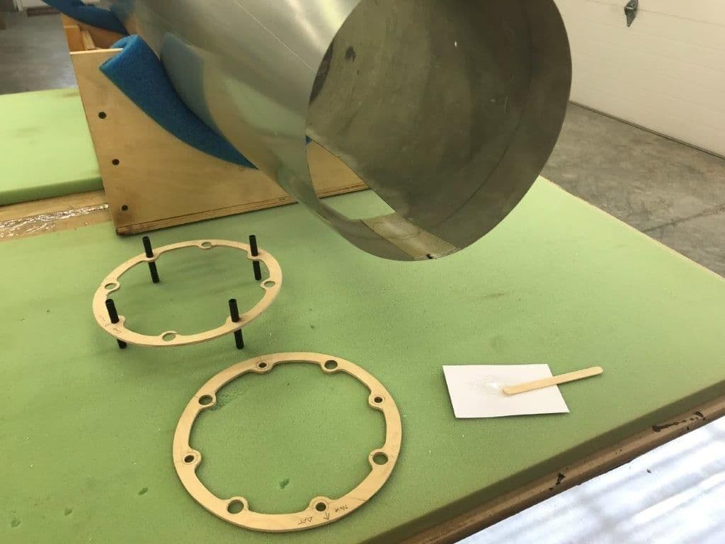
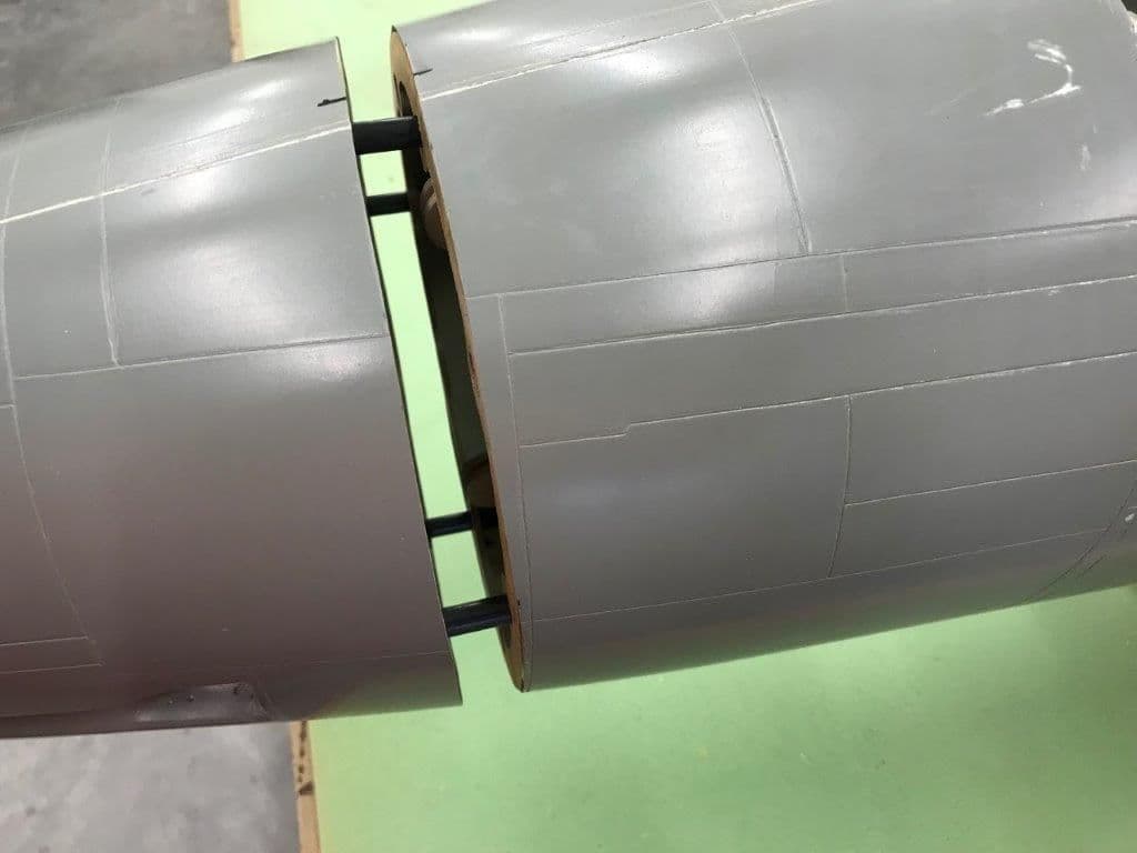
10mm carbon tube sleeves will provide support for the nose cone behind the former and ensure alignment.
10mm sleeves cut and ready
10mm sleeves test fit to 8mm guide pin tubes. The sleeves will be spacers between formers.
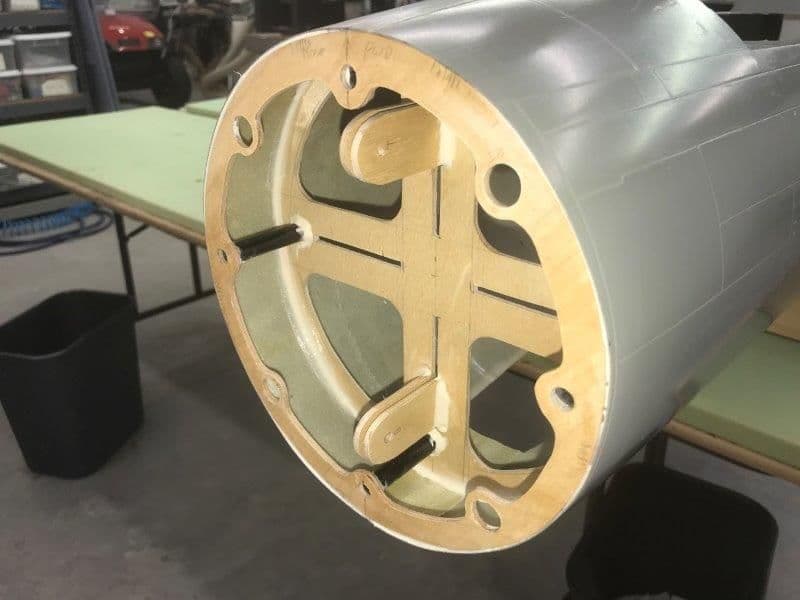
Nose cone former installed to front former and sleeves installed behind front former
Nose cone former still slides in and out ok with sleeves installed
Nose tray former dry fit behind sleeves and pressed forward. 10mm sleeve tubes butt joint to rear former and provide spacers between formers. So far everything seems to be working according to plan.
10mm sleeves cut and ready
10mm sleeves test fit to 8mm guide pin tubes. The sleeves will be spacers between formers.
Nose cone former installed to front former and sleeves installed behind front former
Nose cone former still slides in and out ok with sleeves installed
Nose tray former dry fit behind sleeves and pressed forward. 10mm sleeve tubes butt joint to rear former and provide spacers between formers. So far everything seems to be working according to plan.
10-14-2018, 05:11 PM
#97
Thread Starter
My Feedback: (20)
Everything tacked together ready to test alignments by sliding nose former in and out.
After epoxy set up I tried to pull the front former out and it stuck on the 3 o'clock pin. Do to my not so straight cuts some epoxy leaked inside the sleeve and got it stuck.

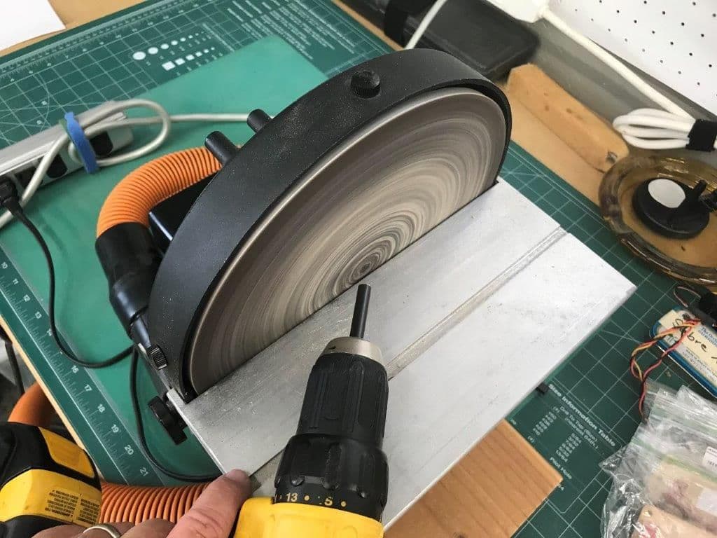
Front former removed and epoxy cleaned out with Q-tips, acetone, and a perfect sized Permagrit round file. I tested the slip fit with another 8mm carbon tube
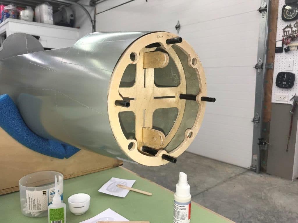
After the fix the front nose cone former was slipped back in it worked ok
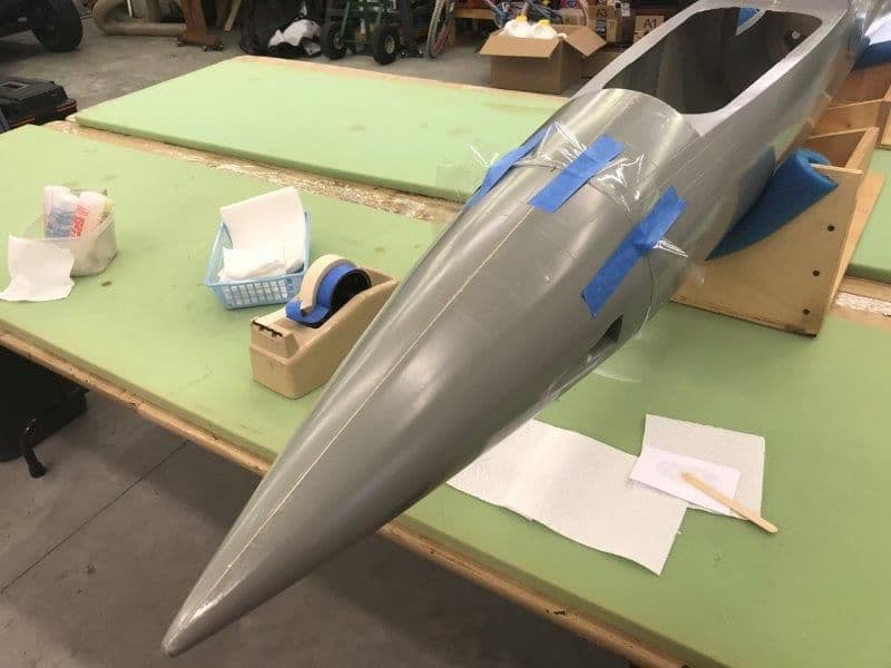
Everything tacked in and sliding in and out OK. I'll let it cure and attach the nose cone next.
I hand held the nose cone over the front former to see what it looked like. I think it will be close but probably will need some body work to make it perfect. I will adjust the panel lines to match the cut line when doing finish work later.
I waited to install the magnets because they seem really strong and I did not want them to pull out the formers because the magnets would not let go. I did not want to install all 4 sets and then realize I may only need one or two. To be continued...
After epoxy set up I tried to pull the front former out and it stuck on the 3 o'clock pin. Do to my not so straight cuts some epoxy leaked inside the sleeve and got it stuck.
Front former removed and epoxy cleaned out with Q-tips, acetone, and a perfect sized Permagrit round file. I tested the slip fit with another 8mm carbon tube
After the fix the front nose cone former was slipped back in it worked ok
Everything tacked in and sliding in and out OK. I'll let it cure and attach the nose cone next.
I hand held the nose cone over the front former to see what it looked like. I think it will be close but probably will need some body work to make it perfect. I will adjust the panel lines to match the cut line when doing finish work later.
I waited to install the magnets because they seem really strong and I did not want them to pull out the formers because the magnets would not let go. I did not want to install all 4 sets and then realize I may only need one or two. To be continued...
10-15-2018, 05:03 PM
#98
Thread Starter
My Feedback: (20)
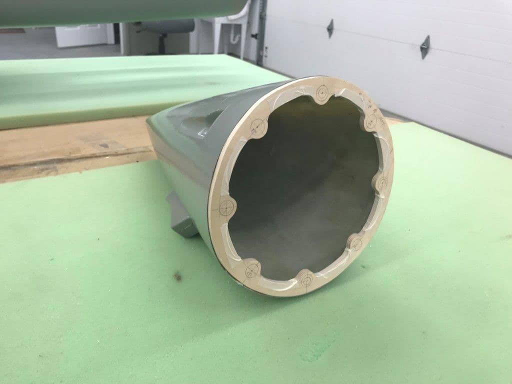
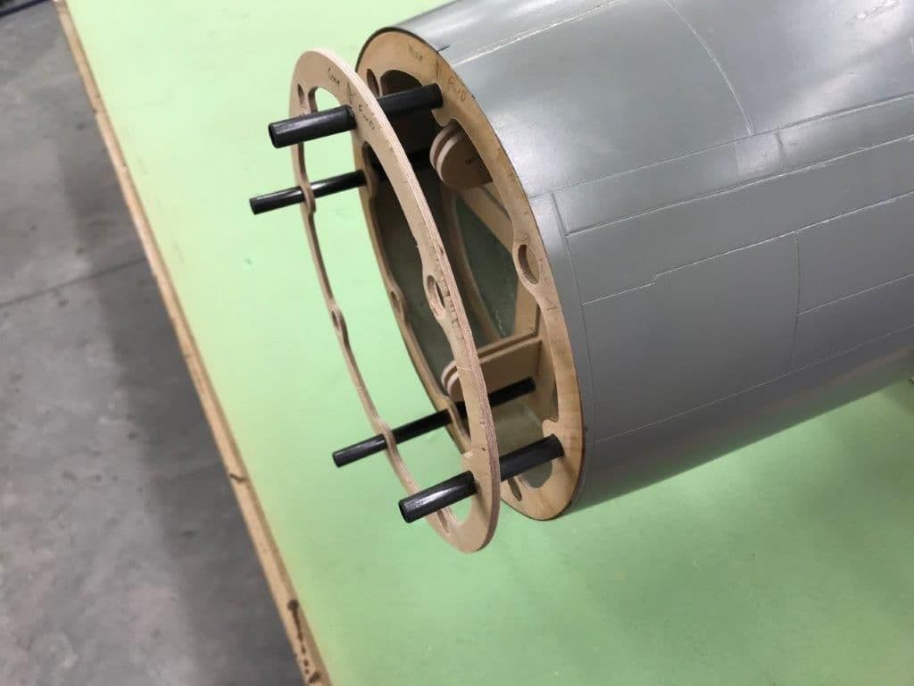
The next steps were to attach the nose cone to the former and secure all joints with hysol
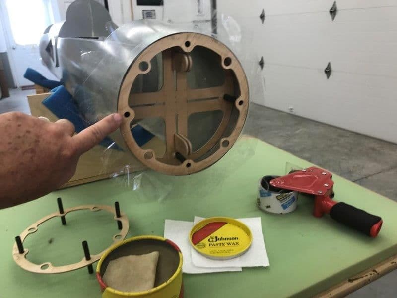
I applied clear packing tape to the fuse front former to prevent epoxy from sticking the two parts together. I then applied wax around the edge of the tape by finger tip applicator.
5 min epoxy was applied to the inside of the nose cone and the nose cone former in four spots that would not drip on the guide tubes. Then the formers were pressed together and the nose cone placed over the nose cone former and taped in place.
After the 5 min epoxy cured the former the nose was pulled off and tape removed. So far so good, it works great.
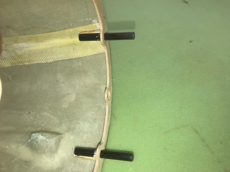
Blocks of wood were installed under the guide tubes to stiffen and attach the tubes to the fiberglass cone and tacked in with CA
I applied clear packing tape to the fuse front former to prevent epoxy from sticking the two parts together. I then applied wax around the edge of the tape by finger tip applicator.
5 min epoxy was applied to the inside of the nose cone and the nose cone former in four spots that would not drip on the guide tubes. Then the formers were pressed together and the nose cone placed over the nose cone former and taped in place.
After the 5 min epoxy cured the former the nose was pulled off and tape removed. So far so good, it works great.
Blocks of wood were installed under the guide tubes to stiffen and attach the tubes to the fiberglass cone and tacked in with CA
Last edited by Viper1GJ; 10-15-2018 at 05:06 PM.
10-15-2018, 05:18 PM
#99
Thread Starter
My Feedback: (20)
Hysol was applied to all joints
Was difficult to get hysol inside the nose but finger applicator worked again
Hysol on front of formers
Hysol from inside fuse looking forward
Everything cured and sliding tubes still work good. I actually thought it was pretty cool.
Some minor body work is needed around the joint but overall I'm happy with the results. Next step is to install the magnets.
10-15-2018, 05:21 PM
#100
Thread Starter
My Feedback: (20)
I just wanted to make sure everyone knows the credit for the ideas in this build are not mine. I'm not an innovative guy but I can copy smart guys ideas. I studied lots of photos from B-1 Bob's videos, Joe Grice's shop and blogs, and invaluable photos from Phil Clark at Fighteraces in the UK. Most everything here was copied from these guys work. Many thanks to all of them for their documentation and help.
Gary
Gary
Last edited by Viper1GJ; 10-16-2018 at 04:25 AM.